





One bit, two cutting directions
A laminated panel can leave the router operator with an annoying choice. An upcut spiral clears chips well and usually protects the bottom face, but it may lift fibers or chip the top laminate. A downcut spiral presses the top surface cleanly and can damage the underside when it breaks through. A compression router bit puts both flute directions into the same cutter.
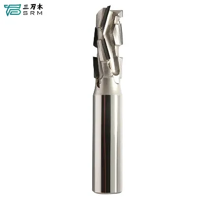
The lower section near the tip cuts upward. Above the transition, the helix cuts downward. During a properly positioned through-cut, both actions direct fibers toward the center of the board rather than pulling them away from the two finished faces. That is why compression geometry is widely used on double-sided melamine, veneered plywood, laminated panels, and cabinet parts where both edges will remain visible.
The geometry is clever, but it is not automatic insurance against tear-out. The first pass depth, flute transition, material thickness, tool diameter, machine rigidity, and cutting conditions still decide whether the bit is working as intended.
The first pass must reach the compression zone
The most common setup error is cutting too shallow. If the first pass stays entirely within the upcut section at the tip, the tool behaves like an upcut bit and can chip the top face. The downcut portion must enter the workpiece before the top surface receives the intended downward shearing action.
Feisite notes that the upcut length near the tip is commonly related to the cutter diameter, though the actual transition length varies by tool. Do not estimate it from a catalog photograph. Check the drawing or measure the cutter, then set the first cutting depth beyond that transition while keeping the pass appropriate for the machine, tool, and material.
This is also why a shallow groove may need a short-upcut or mortise-compression design rather than a standard compression bit. Forcing a normal compression tool into a cut that never reaches the downcut section defeats the reason for choosing it.
Compression, flush trimming, and bearings are different choices
Several product names overlap in search results, which can make selection confusing. A compression cutter describes flute direction. A flush-trim cutter describes the job: bringing one edge level with a template or another surface. A bearing describes how the cutter is guided. One tool can combine these features, but the terms are not interchangeable.
A compression router bit with bearing can follow a template while applying opposing cutting directions to the workpiece. Bearing position matters. A top bearing follows a template above the stock; an end bearing follows a reference below it. Feisite's flush-trimming range also shows configurations with bearings at the top, the end, or both positions.
A compression flush trim router bit makes sense when both faces are prone to chipping and a template or reference edge controls the cut. It is less useful when the material orientation, bearing position, or depth places the compression transition in the wrong location.
The phrase flush trim router bit spiral usually signals a search for spiral shearing action in a flush-trimming operation. Before ordering, translate that phrase into a real specification: cutting diameter, cutting length, spiral direction, bearing location, shank diameter, and the material thickness that will contact each flute section.
CNC routing removes the bearing, not the setup questions
A cnc compression bit normally follows a programmed toolpath rather than a physical template. This gives the programmer control over entry, direction, depth, and lead-in, but it also means that workholding and spoilboard condition become part of the edge-quality problem.
Vacuum leakage, a bowed sheet, or debris under the panel can let the material move as the cutter changes direction. The result may look like a tool problem even when the edge geometry is correct. Before changing the bit, check whether the sheet sits flat and whether the machine holds it securely near smaller parts and narrow offcuts.
Entry strategy matters too. A straight plunge asks the tip to remove material immediately, while a ramp or helical entry can spread the load where the toolpath and part geometry allow it. The correct approach depends on the cutter design and machine instructions; compression geometry does not make every entry method equally suitable.
Diameter changes stiffness, chip space, and corner detail
The search phrase 3 8 compression bit generally refers to a 3/8-inch compression cutter. Feisite's corresponding product page also discusses the importance of the short upcut length near the tip and the need to match that length to the intended groove or pass depth.
A larger diameter can provide more stiffness and room for chip formation, which is useful in production routing. It also creates a larger inside-corner radius and removes more material. A smaller cutter reaches tighter details but is less tolerant of deflection, excessive stick-out, and aggressive cutting conditions.
Confirm whether "3/8 inch" refers to the cutting diameter or the shank. They are not always the same. The collet must match the shank precisely, and the programmed tool diameter must match the cutting edge. Small assumptions here become visible errors in the finished part.
Feed, speed, and heat leave clues on the edge
There is no single feed-and-speed setting for every compression spiral router bit. Carbide grade, flute count, diameter, cutting length, router power, machine rigidity, material density, laminate, and the depth of cut all affect a workable setting. Start with the tool manufacturer's data and the machine's limits, then inspect the chips and cut.
Fine dust instead of formed chips can indicate that the cutter is rubbing rather than cutting efficiently. Darkened edges, resin buildup, or a hot tool point in the same direction. Chatter lines and a wavering edge may come from excessive stick-out, weak workholding, tool deflection, or a worn collet-not merely from the programmed feed rate.
Do not try to rescue a dull edge by slowing the feed indefinitely. More rubbing can create more heat. Check the cutting edge under good light, clean resin with a method suitable for the tool, and replace or service the cutter when edge wear begins to affect both faces.
Match the bit to the actual cut
For a through-cut in double-sided laminated sheet, confirm that the tool's upcut section stays below the top face while the downcut section engages the upper surface. For a shallow pocket or groove, check whether the cut ever reaches the compression transition. For template work, add bearing position and reference-surface access to the decision.
Then look at the production details: minimum inside radius, material thickness, allowance for the spoilboard, required edge finish, machine collet, and planned pass depth. A tool labeled "compression" may still be wrong if one of those conditions falls outside its working geometry.
The right cutter is the one whose transition sits in the right place during the real cut. Once that is established, good workholding and sensible cutting conditions allow the opposing flutes to do what they were designed to do-leave both faces cleaner in a single routing operation.
Tags: compression router bit, compression flush trim router bit, flush trim router bit spiral, compression bit, compression router bit with bearing, compression spiral router bit, cnc compression bit, 3 8 compression bit